|
Abstract: Addressing Small Cell Issues In order to deploy 5G, the next generation of mobile network architectures that promises increasing speeds and lower latency, the network must be densified. Densification implies more cell sites in more locations and getting the signal closer to the users. This means significantly more small cells – there is simply no choice other than to put more radios into the network. |
Table of Contents
Executive Summary
Challenges in deploying small cells
Figure 1: U.S. Actual Outdoor Small Cell Installations, 2015-2020
The Challenge of Location
Figure 2: Typical small cell base installation
Challenge of multi-band multi-operator
Table 1: Operator/Band Source Combining Strategy
Figure 3: RF Performance for various combining applications
Combining Solutions for Small Cells
Balancing small size and RF performance
Example small cell solutions
Figure 4: Dual Band functional layout
Figure 5: Dual-band small cell installation
Figure 6: Dual band two sector functional layout
Figure 7: Dual band two sector small cell installation
Figure 8: Neutral host small cell functional layout
Figure 9: Neutral host small cell installation
Table 2: Comparison of small cell configurations
How good is good enough?
Methodology
Disclaimer
About Microlab
About iGR. 14
In order to deploy 5G, the next generation of mobile network architectures that promises increasing speeds and lower latency, the network must be densified. Densification implies more cell sites in more locations and getting the signal closer to the users. This means significantly more small cells – there is simply no choice other than to put more radios into the network.
The problems with deploying small cells are well known in the wireless industry:
- Location – where are all the small cells going to go?
- Backhaul – the small cell must be connected to the rest of the network.
- Power – small cells need electrical power and in some cases battery backup.
- Spectrum – small cells may or may not use the same spectrum as the macrocells in the same area, depending on the architecture and the mobile operators’ situation.
Small cells are not all created equal – and are not all the same physical size. The challenge of location means that small cells must be put in the available space, which may not always be ideal. Small physical size of the components is therefore critical to successfully deploying small cells!
RF performance is also critical – the small cell is part of a larger network and must perform on an equal footing. Good RF performance, low PIM and good isolation must be maintained in the small cell architecture – the demands of 5G and the ability to meet the industry goals for 5G depend on it.
As a result, the small cell components must be both a small physical size and offer the necessary RF performance – compact quality components. This is true for multi-band and/or multi-sector small cell architectures – small cells are no longer limited to single band, single sector solutions.
With small cells, there is a cost associated with RF performance AND small size. These two sometimes-conflicting factors are difficult to co-design into the small cell components.
New products have been able to solve the challenge of both RF performance and size constraints of today’s small cell deployments. Future solutions for tomorrow’s rollouts will take advantage of these new techniques to satisfy the demands of more bands and configurations.
Challenges in deploying small cells
As the demand for mobile data continues to increase in the U.S., the mobile operators will have little choice but to deploy small cells. Macrocell towers have carried the bulk of the mobile traffic for decades, but this is starting to change as more small cells are deployed where the capacity is most needed – close to the consumer. Remember that the original cellular networks were architected to provide voice service to people as they drove across an area. Today, data is king.
Small cells will also be needed to meet the performance goals of 5G – densification of the RAN is necessary in order to get the higher capacity and lower latency 5G promises. And with more data traffic being consumed by people who are stationary or walking in a dense urban area, more capacity is needed at the street level.
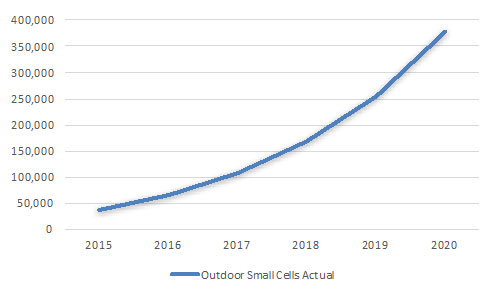
The following chart in Figure 1 shows the forecast for actual outdoor small cell deployments for the U.S. In 2015, iGR estimates that about 36,000 outdoor small cells were deployed. By 2020, iGR expects that a total of nearly 378,000 outdoor small cells will be deployed.
Figure 1: U.S. Actual Outdoor Small Cell Installations, 2015-2020

Source: iGR, 2016
The problems with deploying small cells have been well-documented:
- Location – where are all the small cells going to go? Aside from putting in a new pole at street level, small cells can also be located on roof tops of suitable buildings and street furniture, as well on existing utility poles. What is possible really depends on the restrictions in place in each municipality.
- Backhaul – the small cell must be connected to the rest of the network. Increasingly, this is accomplished with dark fiber but wireless backhaul options are also available.
- Power – small cells need electrical power and in some cases battery backup.
- Spectrum – small cells may or may not use the same spectrum as the macrocells in the same area, depending on the architecture and the mobile operators’ situation. In Europe, it is more common for the small cell to use a separate spectrum band from the macrocells to minimize interference. But either way, the operator must have suitable spectrum available for small cells. Increasingly, small cells will also use multiple spectrum bands.
The Challenge of Location
One of the issues with small cell is that they need to be located to meet the needs of the network, not where a suitable location is available. If the small cell location is compromised, the performance of the mobile network suffers (past tests with small cells have shown a 50 percent drop in network performance if the small cell is not located precisely).
Small cells will also be located in a variety of places: on street lights; on utility poles; on street furniture; on the roofs and sides of buildings; and on dedicated poles at street level. The amount of space available for the small cell equipment in many of these locations is limited – the smaller the actual equipment, the better.
Note that if the small cell equipment is too large, mounting the cell at the required location may not be possible. Thus, if the small cell’s physical size is small, more options will be available as to where the cell can be located. This then presents more options for the network engineers as they design the network architecture.This, however, presents a larger challenge to the equipment vendors. Consider that in New York City, two of the poles at an intersection are reserved for public safety and traffic control – this limits the options available for small cells due to the physical space available.
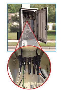
The image below in Figure 2 shows the base of a small cell installation and shows clearly how limited the space is. Every cubic inch of space within the enclosure is at a premium, making component size and dimensions a critical design factor.
Figure 2: Typical small cell base installation

Source: Microlab, 2017
It must also be realized that a single location may be required to host multiple small cells or two bands for one carrier. For example, a neutral host third party may include small cells from two operators at a single location. This may dictate the use of a combiner to minimize the antenna footprint at that location.
Due to these mechanical constraints, it is clear that a “one-size-fits-all” (or most) strategy provides limited options. Vendors must continually adapt and optimize designs to fit within the physical constraintsand achieve desired RF performance for the small cell marketplace. In the example cited in Figure 2, Microlab took one of its standard PCS/AWS diplexers (BK-741E) and created the BK-745E twin unit to address the need for solutions in smaller, more aesthetic enclosures.
Challenge of multi-band multi-operator
The original 3G small cells were single sector and single band. But today, an increasing number of small cell installations use multiple carriers and may have two or even three sectors. This provides a unique challenge since all of the necessary equipment has to be combined into the available space.
The table below describes the signal combining requirements of different applications.With a single carrier, the small cell application requires multiplexers, while in a neutral host configuration, small cell requirements are similar to D-RAN multi-band combiners.
Table 1: Operator/Band Source Combining Strategy
|
Application |
Operator Configuration |
Band Configuration |
Combining Solution |
|
Macro-cell |
Single |
Multi-Band |
Multiple feeder cables to multi-port antennas to achieve combining over-the-air. Each operator has access to their own antennas |
|
D-RAN / Passive DAS |
Single or Multiple (Neutral Host) |
Multi-Band |
Point-of-Interface using combination of multiplexers and hybrid combining into single feeder |
|
Active DAS |
Single or Multiple (Neutral Host) |
Multi-Band |
Active DAS Head-End and Remotes combine all RF into single feeder |
|
Small Cell (carrier) |
Single
|
Multi-Band |
Multiplexers to combine into one or two (Hi/Lo) feeders |
|
Small Cell (Tower-led) (neutral host) |
Multiple (Neutral Host) |
Multi-Band |
Similar to DRAN, using a combination of multiplexers and hybrid combining into one or two (Hi/Lo) feeders |
Source: iGR, 2017
Macro-cells need low loss solutions to maintain RF performance but the macro does not have the same size and weight restrictions as the small cell solutions – there is obviously more space on a cell tower. The macro solution is really driven by economics and the amount the mobile operator has to pay for the tower lease for the size/weight/height of the equipment on the tower.
Active DAS is not as sensitive to loss, since the signal is amplified at the active node. But small cell applications have both size/weight constraints and loss requirements. This presents a unique set of challenges for the small cell, especially when combining multiple bands.
D-RAN is generally both neutral host and multi-band. A Point of Interface (POI) has several ports of combination along with multiple outputs for distribution in the D-RAN architecture. This system tends to be larger in size and have much higher RF losses due to the number of combinations of inputs and outputs. High power radios can overcome these losses to make D-RAN feasible. However, due to the much lower power levels of small cell radios, only a certain amount of loss can be tolerated without affecting capacity and/or coverage. In the case of a small cell, the RF requirements overlap with both macro and D-RAN systems, but, as shown in Figure 2, present a unique combination of trade-offs.
Figure 3: RF Performance for various combining applications

Source: Microlab, 2017
In summary:
- Existing applications have different performance requirements for signal combining
- The current solutions will not necessarily work for small cells because of size constraints
- The necessary trade-offs in small cell signal combining require new solutions that provide both RF performance (loss, isolation, power) and meet the size/weight constraints.
Combining Solutions for Small Cells
Combiners used on macro cells present challenges for small cells:
- On the macro, every RRH has its own antenna port. But a multi-band small cell may have a single antenna, therefore requiring a combiner.
- With a macro or active DAS, combiners are not usually considered – on an active DAS, there is a multiband radio driving the active array.
- Using a combiner in a multi-band small cell presents another mechanical constraint due to the size and space limitations.
- The combiner must meet strict small cell RF performance criteria.
Balancing small size and RF performance
As discussed earlier, small size of the components is critical to the ability of deploying a small cell where it is needed, not just where there is a convenient location. But RF performance is also critical – after all, if a small cell does not have the necessary RF performance, it is not able to do its fundamental job.
An important consideration for small cells is that they are supplementing macro-cell capacity in coverage, as well as filling in dead-spots. As a result, the RF performance of the small cell must match that of the macro-cell – for example, PIM performance of the small cell must match that of the parent macro to maintain the QoS across the entire user connection experience.
For 5G networks, RF performance is even more critical since 5G essentially maximizes the RF potential of the LTE waveform to deliver lower latency and higher bandwidth.And the entire small cell solution must perform – the solution cannot simply have a good antenna or radio and then a poor diplexer, for example.
5G will be unable to meet its performance goals without cell densification – simply, densification is required to execute a 5G architecture. So the industry MUST be able to deploy small cells. And the smaller the cell, the more options there are for location but this cannot happen at the expense of RF performance. A physically small solution with poor RF performance is unacceptable.
The final size-related consideration is flexibility. Deploying small cells is not easy for technical, zoning, permitting and cost reasons. The more flexible the small cell solution is in terms of location, the more likely it is to actually get deployed. Flexibility also extends to configuration – two sector, multiple bands, etc. Small cells will not just be single sector, single band deployments – the limited locations are too valuable for that. A small, high quality diplexerenables multiple configurations without sacrificing RF performance or size, and hence increases flexibility.
Size and RF performance also extends to the connections within the small cell between radio, diplexer and antenna. As the number of bands and sectors increases, so the number of ports and connections also increases, each of which takes precious space.Isolation between the bands is also linked to port number and size – to improve isolation, larger port sizes are required (greater space between ports).
Example small cell solutions
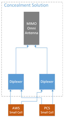
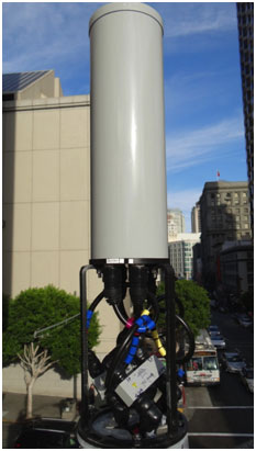
Rather than just a single sector, single band solution, small cells are now being deployed in multiple configurations. Figure 4 and Figure 5 below show the functional layout for a dual band small cell solution and an example installation. In this example, a MIMO omni antenna is fed by two small cell radios (using PCS and AWS bands in this example) through two diplexers. Compact Diplexers and cabling mounted within concealment solution provide low-loss combining for maximum RF transmitted power leading to greater throughput and/or capacity.Diplexers are available for all standard frequencies. Triplexer and Quadraplexer solutions are also available that offer additional flexibility for the many combinations of standard wireless frequencies that are required across the numerous small cell systems.
|
Figure 4: Dual Band functional layout
Source: iGR, 2017
|
Figure 5: Dual-band small cell installation
Source: Microlab, 2017
|
The next example (Figures 6 and 7 below) shows a dual band two sector small cell configuration, again using AWS and PCS bands. In this case, using two directional antennas with 2×2 Hybrids provides the benefit of efficient broadband combining and splitting. By virtue of having and using both outputs, the issue of overcoming a hybrid coupler’s inherent 3dB loss is negated. Hybrid couplers also provide the necessary RF isolation with very low insertion loss of <0.2dB. Figure 7demonstrates the physical installation and clearly shows the limited physical size available for the necessary equipment.
|
Figure 6: Dual band two sector functional layout
Source: iGR, 2017
|
Figure 7: Dual band two sector small cell installation
Source: Microlab, 2017
|
The final example in Figures 8 and 9 below shows a neutral host small cell layout with 3×3 hybrid combiners and a tri-sector antenna to create a quasi-omni site. This type of installation could be used by a third party planning to build a network and then lease capacity to the mobile operators or provide the ability to add future bands or carriers. The use of a 3×3 hybrid matrix coupled with a tri-sector antenna creates a quasi-omni pattern suitable for urban coverage.
|
Figure 8: Neutral host small cell functional layout
Source: iGR, 2017
|
Figure 9: Neutral host small cell installation
Source: Microlab, 2017
|
Table 2 provides a summary of the various small cell configurations and the associated benefits.
Table 2: Comparison of small cell configurations
|
Small cell configuration |
Primary application |
Benefits |
|
Dual-band single sector |
Now considered standard small cell deployment Used to provide capacity and/or coverage at a specific location
|
Compact Diplexers and cabling provide low-loss combining for maximum RF transmitter power Greater throughput and/or capacity Diplexers are available for all standard frequencies Triplexer and Quadraplexer solutionsalso available for additional flexibility |
|
Dual-band dual sector |
Targeted coverage/capacity small cell deployment Larger equipment limits some deployments |
Efficient broadband combining and splitting Using both outputs, hybrid combiner inherent 3dB loss is negated
|
|
Neutral host |
Used by third party network provider leasing capacity to the mobile operators Also used by operators planning to add future bands or carriers
|
The use of a 3×3 hybrid matrix coupled with a tri-sector antenna creates a quasi-omni pattern, suitable for urban coverage |
Source: iGR, 2017
How good is good enough?
One question the mobile industry should discuss is ‘how good is good enough?’ With small cells, there is a cost for good RF performance AND small size. These two sometimes-conflicting factors are difficult to co-design into the small cell components.
Given the number of small cells the industry is planning to deploy over the next few years (upwards of half a million by 2021), cost is an important factor:
- Will the carriers continue to pay for RF performance and small size?
- Or will RF performance be relaxed to reduce costs and maintain small component size?
- Or is RF performance of paramount importance and physical size will be sacrificed to reduce costs?
The answers to these questions will be found over the next 18 to 24 months as the carrier ramp up deployment. Third parties will also deploy small cells and then lease capacity back to the carriers – how will these network vendors balance the RF performance/physical size/cost equation?
Methodology
iGR relied on the following sources when writing this whitepaper:
- Discussions with mobile operators in the U.S.
- iGR’s primary research, reports and forecasts
- Secondary research.
Disclaimer
The opinions expressed in this white paper are those of IGR and do not reflect the opinions of the companies or organizations referenced in this paper. All research was conducted exclusively and independently by IGR.
About Microlab
Microlab is a leader in low PIM (passive intermod) RF and microwave products enabling signal distribution and deployment of in-building DAS (distributed antenna systems), wireless base stations and small cell networks. High performance passive components such as power combiners, directional couplers, attenuators, terminators and filters are developed for broadband applications to support public safety networks, GPS reference signaling, television transmitters and aircraft landing systems. Active solutions from Microlab include GPS signal repeaters for cellular timing synchronization and passive safety monitors for real-time in-building DAS system diagnostics.
About iGR
iGRis a market strategy consultancy focused on the wireless and mobile communications industry. Founded by Iain Gillott, one of the wireless industry’s leading analysts, we research and analyze the impact new wireless and mobile technologies will have on the industry, on vendors’ competitive positioning, and on our clients’ strategic business plans.
A more complete profile of the company can be found at http://www.iGR-inc.com/.


